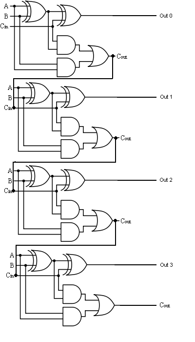
Four Bit Adder Circuit
Four bit parallel adder using full adder Adder subtractor bit circuit logic overflow diagram detection designing questions digital Full-adder circuit, the schematic diagram and how it works – deeptronic
Design a 4-bit combinational circuit incrementer. (A circuit that adds
11+ 4 bit adder circuit diagram 4 bit adder subtractor circuit diagram 4 bit binary adder
Four bit parallel adder using full adder
Adder bcd cheggcdnAdder subtractor binary circuit bit diagram logic block coa javatpoint mode 4-bit adder and subtractor circuit explainedAdder subtractor bit circuit ripple carry diagram logic using project build only computing learn let digital its indie electronics.
Download 4 bit adder circuit stick and logic diagram4-bit adder-subtractor in digital circuit Bit binary bits output geeksforgeeks incrementedUsing bit half adders four circuit logic digital schematic circuitlab created electronics.

Binary adder and binary addition using ex-or gates
Adder circuit full logic using digital boolean implementation diagram implement functionLet's learn computing: 4 bit adder circuit 4 bit binary adder circuit diagram4-bit binary adder-subtractor.
😊 four bit parallel adder. 4 bit binary adder circuit / block diagramCombinational and sequential design of a 4-bit adder. (a) ha circuit The answer is 42!!: four bit full adder tutorialDigital logic design: full adder circuit.

Adder circuit diagram schematic bit full works figure
4 bit binary incrementer4 bit adder subtractor circuit diagram Digital logicAdder binary bit addition carry python will using bits input gates program sign ripple.
How to make 4 bit adder circuitFull adder circuit diagram Electronic – 4-bit decrementer using four half adders – valuable tech notes🎉 4 bit parallel adder theory. 5.9: four. 2022-10-30.
Digital logic
Adder binary bit circuit example full truth table rtl understand will need register adders use discuss details4-bit adder subtractor Let's learn computing: 4 bit adder/subtractor circuitDesign a 4-bit combinational circuit incrementer. (a circuit that adds.
Adder half xor rangkaian logic ripple adders transistor kombinasi2 bit adder circuit diagram Adder bit full four logic gates byte 4bit nand boolean values possible nor not possibilities hold answer trick function knownLogic gates.

4 bit full adder circuit diagram
4 bit binary adder circuit diagram🎉 4 bit parallel adder theory. 5.9: four. 2022-10-30 Circuit adder bit diagram logic computing learn letAdder bit circuit half make full logic gates first questions electronics cout second puzzle connecting solved which.
Adder bit parallel four circuit diagram binary subtractor logic digital full block example geeksforgeeks detailed discussionAdder bit using full circuit adders half four circuits implementation watson figure just box single into outputs latech edu .


Let's Learn Computing: 4 bit Adder Circuit

Four Bit Parallel Adder Using Full Adder

Watson

logic gates - How to make 2 bit or more half adder circuit - Electrical

Let's Learn Computing: 4 bit Adder/Subtractor Circuit

4 Bit Full Adder Circuit Diagram

4 Bit Binary Adder Circuit Diagram - Wiring Diagram